Creating a Diagram
If you haven't followed the Getting Started guide, we recommend you acquaint yourself with the basics by following it. It will guide you on how to create a simple diagram, making the contents of this page much easier to understand.
A diagram is made of nodes connected by links. Nodes are made of input and output sockets and links always connect output sockets from one node to inputs of another. This means that you can't create loops (feedback) using links, for that you must use Memories.
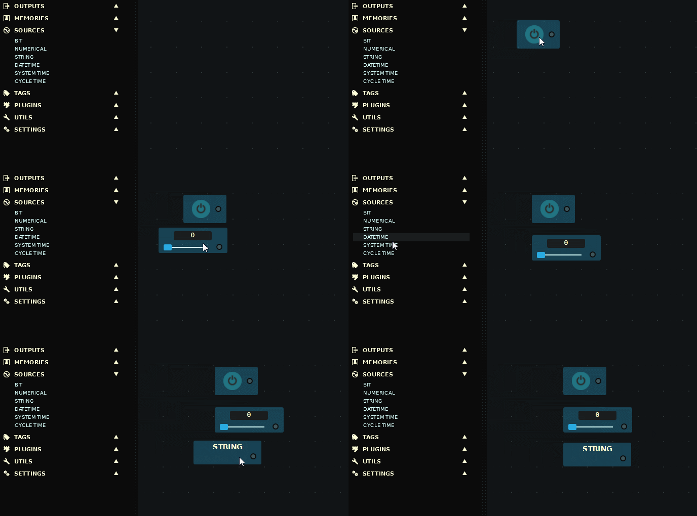
You create a diagram by Dragging nodes from the Nodes Palette into the canvas, alternatively, you may Double Left-click on a palette node to create it.

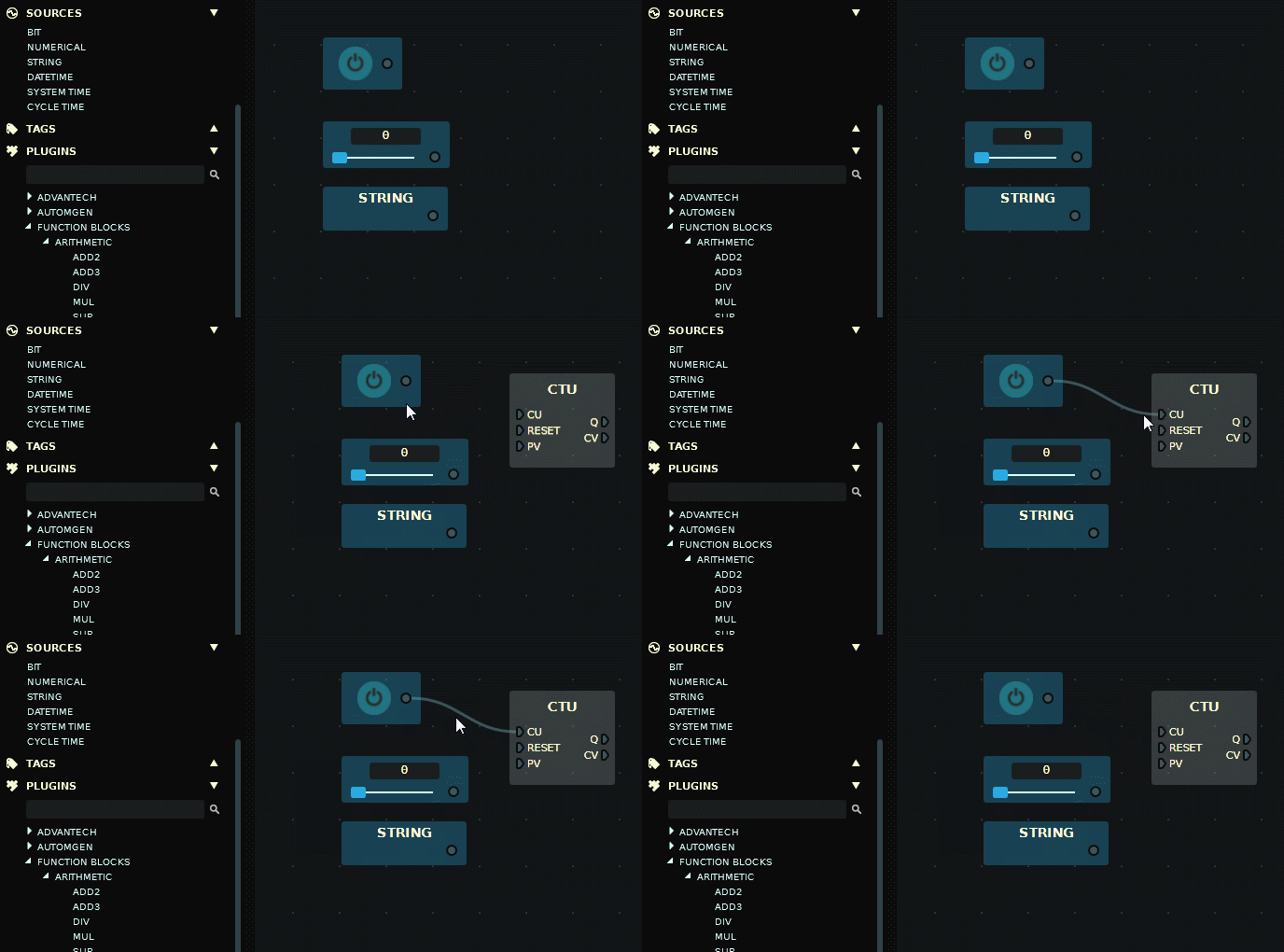
After placing and arranging nodes, you create links between them by clicking on a node's output socket and dragging it to the target input socket. Note that you can only create links between compatible data types, for example, you cannot link a Boolean value to a node's socket which expects a number (byte, short, int, long, float or double). Although, when a node's input socket expects a numerical value it will accept any data type and will automatically convert it.

To delete a link, Left-click and press Delete.
Feedback 
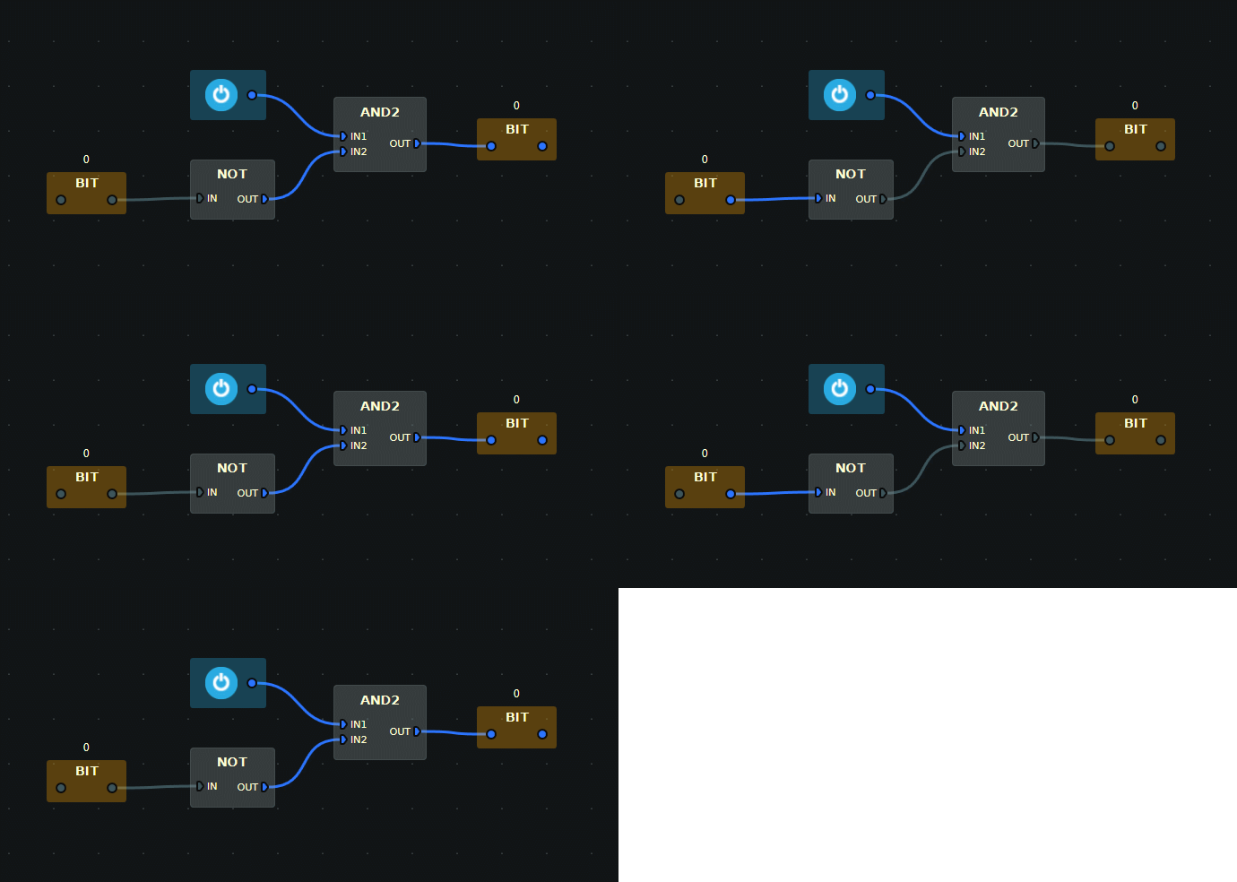
You can't create links between output and input sockets, this means that you can't create loops (feedback) in your diagrams by using links directly. To create a feedback you must use Memories nodes with the same address.
When several memory nodes share the same address, an upstream memory node will get the value of the most downstream node on the next diagram update cycle. On the following example, the diagram cycle time was set to 1000 ms (1 second) to make this behavior easier to observe.
